

3.1 Construction quality assurance
This section should discuss construction quality assurance measures that will be implemented to ensure proper installation of the PVMS. A description of common construction quality assurance measures is provided below and should be included, as appropriate. Each PVMS should be installed in accordance with the manufacturer’s requirements.
Inspections with recordkeeping are necessary during installation to document that the VMS components were properly installed, meet the design specifications, were not damaged during construction, and remain leak free so that sub-slab vapors do not enter the building envelope. The inspections must account for construction phases and conditions that may affect the integrity and performance of the VMS and are detailed in Section 5.0.
3.1.1 Surface preparation
This section should identify any measures specified or required by the product manufacturer for the preparation of any surface where a vapor barrier or epoxy coating will be installed. This includes, but is not limited to:
For vapor barriers:
- Compaction requirements for subsurface base materials.
- Area will be clean, dry, and free of any debris and sharp objects that could puncture the vapor barrier.
- Any protective layer(s) required beneath the vapor barrier, such as non-woven geotextile fabric.
For epoxy coatings:
- Relative humidity of the concrete surface will be measured to ensure moisture content is acceptable prior to coating application.
- Manufacturers recommended surface preparation of the concrete surface will be completed prior to the application.
- Surface of the concrete will be clean, dry, and free of cracks, chips, and greases or compounds that may prevent adhesion.
This section should also describe and identify how the installation and site conditions will be documented to have been met and when inspections and oversight will occur. It is recommended that the documentation include written logs, observations, and photographs that confirm the inspection of the material prior to the installation of the liner.
3.1.2 Surface restrictions
If a vapor barrier that consists of a liner will be installed, this section should discuss how any necessary precautions identified in Section 2 will be implemented and confirmed throughout the installation process to help ensure that the liner will not be punctured or damaged.
If an epoxy coating is applied, this section should describe how surface restrictions (i.e., traffic control) will be implemented to allow the coating to fully cure.
Note: Daily field logs, oversight, and photographs are highly recommended when the liner is exposed without a protective cap or until the epoxy floor covering has set to confirm that any restrictions are complied with, or when not, what measures will be undertaken to confirm the integrity of the liner material.
3.1.3 Smoke testing and tracer gas testing
Smoke Testing and Tracer Gas Testing is used to identify the location of any breaches within a vapor barrier during the installation process. This type of testing involves injecting non-toxic smoke beneath a vapor barrier through a passive vent riser, test port, or through a small hole cut into the vapor barrier and checking for any visual sign of smoke penetrating the vapor barrier. Any breaches, such as imperfections in a vapor barrier or utility penetrations that have not been properly sealed should be identified and repaired. When repaired, that portion of the vapor barrier should be retested to confirm no smoke is able to pass through the vapor barrier. The area of coverage for smoke testing is highly variable depending on several key factors; therefore, in addition to referencing manufacturer recommendations, this section should identify how the area of each smoke test will be verified and documented in the field, how the results are documented, and how each repair will be verified to be effective.
Testing must provide sufficient coverage to assess every penetration, seam, and termination of the vapor barrier. Smoke testing should also be performed when field oversight identifies activities that, based on the specifications identified in Section 2.2, are likely to have punctured the liner. When field inspections and oversight indicate that the liner may have torn or been perforated, additional smoke testing is necessary.
3.1.4 Thickness requirements and verification
Spray-applied vapor barriers and epoxy coatings have minimum thickness requirements for proper installation which are specified by the product manufacturer. This information should be provided in this section.
There are two main methods used to confirm and verify the thickness of an applied material (see Section 3.1.4.1 and 3.1.4.2). The design firm should identify the method(s) used to confirm the thickness of an applied material(s), briefly describe the process, identify how the sampling locations will be documented, how often a sample will be collected, and discuss how the resulting information will be used for thickness verification. If thickness is measured and determined to be too thin, then additional spray-applied vapor barrier material should be added to the area. That process should also be described in this section.
3.1.4.1 Coupon Testing
If spray-applied vapor barriers are installed as a component of the PVMS, coupon testing is performed to confirm that the thickness of the spray-applied vapor barrier meets the manufacturer’s design specifications and installation requirements. Coupon testing is performed by collecting a small sample of the liner (i.e., a coupon) and measuring its thickness with a caliper. When performing coupon testing, it is important to document the location where each coupon sample was obtained from and the thickness of each coupon sample.
Note: The number of coupon samples that are necessary to adequately verify vapor barrier thickness should be based on the following:
- One coupon sample for every 500 square feet of applied surface area unless any of the following occur which then requires the collection of additional coupon samples:
- A change in spray pattern or break from the applicator due to a change in equipment or period of rest.
- Each wall or vertical surface greater than 64 square feet; and
- Each drum or vat if the area of coverage is less than 500 sq ft.
3.1.4.2 Wet film gauge testing
A wet film gauge is a tool used to measure the thickness of a coating after it has been applied and is typically used with the application of surface epoxies. The gauging tool measures thickness in units of mils, which is equal to one thousandth of an inch. The location and thickness of each location where the application is gauged should be carefully documented.
How to determine mil thickness
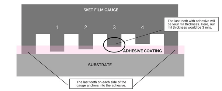
Note: The number of measurements that are necessary to adequately verify thickness should be based on the following:
- Every per 150 square feet unless any of the following occur which then requires the collection of additional gauging locations:
- A change pattern or break from the applicator due to a change in equipment or period of rest.
- Each wall or surface greater than 64 square feet; and
- Each drum or vat or container if the area of coverage is less than 150 square feet.
3.1.5 Material estimation verification
This section should provide an engineer’s estimate of the estimated quantities that will be used to meet the established requirements. The estimated quantities should be provided so that during the installation process a comparison may be made to the actual quantities used.
3.2 Oversight and documentation of PVMS installation
Inspection of the PVMS system components should be performed during the installation process. Oversight performed and the resulting documentation are essential to demonstrate that a PVMS was installed appropriately and meets the design specifications established in Section 2. This section should include a description of the planned oversight that will be performed and the construction quality assurance measures that will be incorporated and documented throughout the installation process. Justification of the level of oversight must be included.
Obtaining photo documentation of specific features during the PVMS installation process is an efficient way to document observations made during the installation process. Photos should be obtained for key features of interest. Photographs help to document the quality of work completed during the PVMS installation process. Specific attention should be paid to details such as adequate sealing around utility penetrations, areas where repairs were performed, wall terminations, and seams or welds. Once the installation process is complete, it may not be possible to document this information.
Note: Providing oversight to confirm site conditions are consistent with those specified in PVMS design will increase the likelihood that the PVMS will be installed in accordance with the design plan.
Recording details such as those listed below can be used as documentation to support future submittals.
- Date
- Weather Conditions
- Materials Quantiles of Products
- QA/QC Measures Performed
- Measurements and Readings Locations and Results
- Necessary Repairs and Correction Documentation
- Samples Collected (when warranted)
- Photographs
Key supporting information
- It is not anticipated that any figure is warranted, though an example of a daily field log, photographic logs, or other specific documentation may be appropriate as an attachment.